Articles
Maxwell GeoSystems maintain an active library of media articles and copies of its latest contributions to trade journals.
Settlement Due to Under-Drainage: Transient Characteristics and Control Measures
The flow of water into tunnels and the lowering of ground water levels is a transient process governed by the permeability of the ground, the storage of the various reservoirs and the available recharge. The resulting settlement is a function not only of the compressibility of the deposits but also of their ability to drain. This paper draws on a large database of information both from Hong Kong and worldwide to examine the transient behavior of the ground during drawdown and reviews the effectiveness of surface recharge systems.
1. Introduction
Under drainage is the process by which a tunnel (sink) drains water from an aquifer which has limited immediate recharge. This can be as a consequence of an impermeable upper layer, an aquiclude, and/or due to lateral recharge being restricted. The net result of under-drainage is a lowering of groundwater pressure in materials, some of which may be compressible. This paper looks beyond the conventional steady state view of under-drainage and addresses transient characteristics. It summarises the authors’ experience of rocks exposed in an uninterrupted transect across 20km of Hong Kong during mining of the Strategic Sewage Disposal Scheme Phase 1.
2. Fluid Flow In Hong Kong Strata
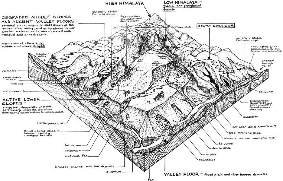
Hong Kong is a mountainous region with a thick mantle of residual soil and saprolite, draped in complex sediments comprising intercalations of terrestrial colluvium and alluvium with marine sedimentary deposits. Reference to Fookes (2007) illustrations on geomorphology and Leeder (2011) on sedimentary process show immediately the difficulties faced when attempting to assess the impact of a sink installed within this ground. Imagine a thick sequence of marine deposits overlaying the model shown in Figure 1 and it is clear how inadequate conventional analyses are. Predominantly models are two dimensional or if three dimensional they are so simplistic as to be misleading. The following provides a list of the typical characteristics of materials and their impact on the analysis of ground water flow: Water: Tests carried out during SSDS Phase 1 shows that three types of ground water exists in Hong Kong. Freshwater from rainfall percolating downwards, seawater percolating sideways as the freshwater table varies and deep groundwater which has been in place for millions of years and whose chemistry changes in response to hydrothermal incursions from depth, through diffusion and through in-situ reaction with the ground. Seawater and fresh water may percolate downwards only after this ancient water is displaced. The characteristics of seawater and freshwater are well known but the deeper water is characterized by very high biochemical oxygen demand, high Fe content and conductivity, the natural consequence of which is to promote corrosion and rapid deposition of salts, in particular Ferric Hydroxide on exposure to air. Rock: May be massive or closely jointed but back analysis shows that bulk rock permeabilities in Granites and Tuff vary from 5 x 10⁻⁸ m/sec to 5 x 10⁻⁷ m/sec with an average of 1 x 10⁻⁷ m/sec being equivalent to steady state tunnel inflow of 1 litres/minute/metre of tunnel at 100m of head. The porosity of igneous rocks is considerably less than 1% (except for some rare tuff breccias) and increases with weathering. Flow tends to occur along discontinuities which may be cooling joints, un-roofing joints, tectonic joints or volcano-sedimentary features such as tuff breccias. Typically. rapidly cooled igneous/volcanic rock tends to be more closely jointed and more permeable than granites cooled gradually. Those rich in volatiles such as Rhyolites may also have open structures and close jointing and as a result are difficult to drill. The actual permeability in rock depends as much on the size of the discontinuities as on their connectedness and this is most influenced by the extent to which mineral deposition has or has not taken place. Deposition of quartz, calcite, chlorite, various iron compounds and clays minerals including the ubiquitous kaolin are hard to predict and occur in several phases. Faults may not always be the main conduits so often assumed since they are frequently observed to possess significant clay in the gouge and decomposition and therefore annealing on one or other side of the fault plane. These may sometimes behave as dams and it may be that the inrush of water experienced on hitting faults is a function of the high head and not necessarily of high permeability.
Decomposed rock and Saprolite: For the purpose of this classification we group all decomposed rock from grade IV to VI within this category and as such the permeability can vary typically from 1 x 10⁻⁷ to 5 x 10⁻⁶m/sec. Porosity varies from <5% to up to 15%. Flow in decomposed rock is governed by relict fissures and soil pipes which may or may not be connected since the arrangement of soil pipes may also be governed by the terrain of the decomposed rock surface. Colluvium: The distribution of colluvium is dependent on the palaeogeomorphology of the decomposed rock/rock surface even where hidden by other sediment. Colluvium may be intercalated with alluvium at the margins of upstanding areas of rock. Colluvium can be highly heterogenous and comprise transported boulders and/or chaotic slide materials on slopes and/or debris flow materials which are strongly channelized in their upper reaches but are spread thinly over wide areas at their distal ends. The key characteristic of colluvium is that it is discontinuous and is unlikely to behave either as an aquiclude or as a significant pathway for water migration. Alluvium: Alluvium is an often mis-used catch all phrase and is often considered to be a single material for the purpose of hydrological assessment. In reality this is a complex arrangement of gravels, sands, silts and clays which form an alluvial plain. Permeabilities can range from 1 x 10⁻⁵ m/sec in gravels to as low as 1 x 10⁻¹⁰ m/sec in consolidated clays. Porosity can also vary from 20% to 40%. Of all materials it is the alluvium which most influences the movement of groundwater during under drainage. Marine deposits: Marine deposits are deposited over the alluvium during sea level rise and may vary from well winnowed medium sands to silts and clays depending on the energy of the marine environment in which they are deposited. Small amounts of clay and silt can significantly affect the permeability and particle size distribution curves should be used to extend in situ and lab permeability tests in order to estimate relative permeability. Fill:It is often assumed that fill is highly permeable, however this will very much depend on the type of fill, marine sand or CDG, and level of compaction. As a result permeability can vary from 1 x 10⁻⁶ to 1 x 10 -5 m/sec. The vertical permeability of the fill will also largely be controlled bv layers of re-precipitated mud which may have accumulated at the base of the reclamation and within the reclamation during storm periods. It is often assumed that dredged channels for seawalls are always pathways for recharge whereas in reality the foundation alluvium material may not be particularly permeable even discounting the potential for considerable thickness of re-precipitated mud. Artificial materials: The presence of linear construction projects, which often comprise kilometers of diaphragm wall, will severely affect the natural drainage paths within the soil strata. Assumptions of lateral drainage, particularly from hillside catchments, will be incorrect. The effect of retaining systems on natural drainage has been seen on countless projects, where installation of D-walls has resulted in elevated water levels and significant (up to 5m) differences in piezometers from one side of an excavation to another. Nevertheless in most designs water pressure is assumed to exert evenly on both sides of an excavation.
3. Modelling And Predicting Fluid Flow
3.1 Simple Models
The conclusion appears to be that it is too complex to model. Certainly any simple model cannot be considered to be in any way to represent what will happen except if that model is constructed on a small scale and a lot of GI data is available to confirm that the materials between source and sink are hydrogeologically consistent. On a basin scale analyses will be grossly misleading. There is still room for modeling but only as a test of sensitivity. Particular factors to identify are: What are the key drainage materials? What is the recovery time likely to be for various assumptions of recharge boundary,aquiclude permeability and thickness? What is the specific storage in these key materials and how will they be affected by depressurization? Once these key permeable horizons have been identified it is necessary to try and identify where they are situated, the connectivity between them, and the potential rock conduit (if the tunnel is in rock) and to areas which may be sensitive to depressurization.
3.2 Mapping fluvial and alluvial networks
A concept that is common in geology is the facies map. Used frequently in petroleum and groundwater exploration this maps units not by their geological unit or formation name but by material or origin. A map therefore can represent the distribution of material type at a particular time, depth or relating to a particular stratigraphic event ie an unconformity.
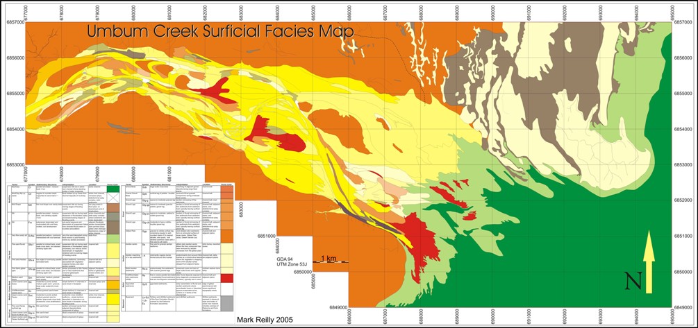
Such maps are easily prepared from GI logs by picking a chronostratigraphical boundary and mapping the distribution of material types at that boundary. Key horizons are: the material at the base of the alluvium which is unconformable on the decomposed rock and the alluvial material immediately below the base of the marine deposit which sits unconformably on the alluvium. These two horizons will determine the connection to the rock/decomposed rock flow paths and the locations where depressurization will affect the compressible marine deposit. Facies maps provide an assessment on whether the assumptions used in numerical modeling are likely to be correct. Consider the example in Figure 2. For any arbitrary section, is it sensible to assume all the flow is in the line of the section? Is it sensible to assume that the materials identified are in homogenous layers or will flow tend to be concentrated on particular pathways? In reality fluvial systems are far too complex to be modeled on a catchment scale by simple layer cake models. It is far better to identify a realistic hydrogeological model using basic geological tools and relationships and use this as a basis for simpler experiments to investigate the potential sphere of influence of a groundwater sink and the likely consequences.
3.3 Transient vs Steady State
When water is encountered in a tunnel the flow path is immediately determined by the high permeability geological units. The speed of reaction is determined by the porosity of the medium. In rock, highly connected and conductive pathways can produce drawdowns in piezometers several hundred metres away whilst rock piezometers several 10’s of metres away remain unchanged. Rock fracture porosity is so low that a small quantity of water extracted will have a large effect. The effect will be dependent of how deep within the rock the piezometer tip is placed ie away from recharge from nearby more permeable horizons, and how close this is to the tunnel sink. Commonly these preferential water pathways are associated with deep weathering and some recharge will be drawn from overlying saprolitic soils producing depressurization and consolidation. Whilst compressibility is relatively low, these layers can be thick and consolidation is rapid, typically completed within 2-3 months. The most important pathway for depressurization is that which connects fissure flow in the rock to highly permeable gravel and cobble horizons in the lower alluvium. From here connectivity is assured since the deposits originated in a fluvial/alluvial environment and are probably still operating as conduits for ground water drainage.
3.4 Typical observations
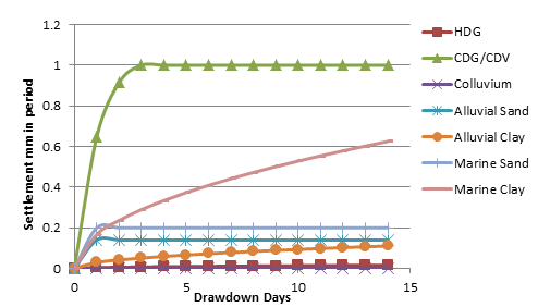
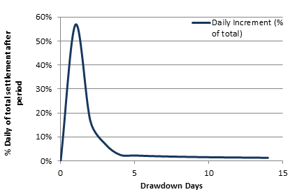
For open tunnels in rock the first interception with water is through probe holes. These will produce immediate drawdowns in some rock piezometers which will recover once grouted. Drawdown in overlying compressible deposits will not occur if the holes are allowed to drain for periods of only a few hours. Longer periods of drainage may start to produce drawdowns which will start consolidation at rates governed by the permeability of the consolidating material. The amount of consolidation will depend on the length of time the change in stress operates. This is termed drawdown days and is determined by the length of time the sink is in operation and the rate at which the ground will recharge once the sink is removed Figure 4. In the example in figure 3, the rate of discharge is related to the permeability of the aquifer tapped by the sink and in this case the initial rate of drawdown is chosen to be 2m/day and it is stopped after 2 days. The rate of recharge is determined by the surrounding permeabilities at the recharge boundaries and the specific storage of the aquifer. It is set at 2/3 of the drawdown rate in this example which was typical of the recovery of piezometers in SSDS after transient depression due to probe hole drilling. Note that actual recharge rates may be many times lower than this value.
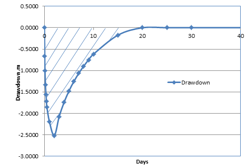
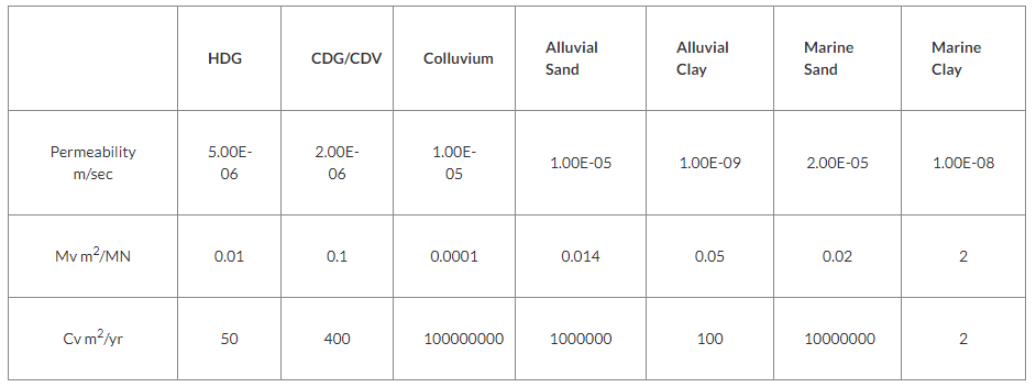
Settlement can be calculated by integrating the curve for the number of drawdown days and applying simple one-dimensional consolidation theory the result of which are shown in Figure 4. Table 1 summarises some typical soil compressibility for Hong Kong materials. Those for materials with high permeabilities are taken from the results of field observations including both drawdown related consolidation and rebound. It is noticeable sthat the results of back calculation of Mv and Cv values for decomposed soils suggest significantly higher compressibility and lower coefficients of consolidation for decomposed soils particularly within fault zones.
4. Examples From Ssds Tunnels
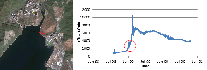
The following example is taken from SSDS tunnel the details of which are published in Territory Development Department (2000). Tunnel C was excavated at -90mPD between Tseung Kwan O and Kwun Tong across Junk Bay. Several instrumented reclamations were nearby as shown in Figure 6. In this example water inflow increased markedly from chainage 700 to 800 and was constant up to chainage 1200 (shown in red).
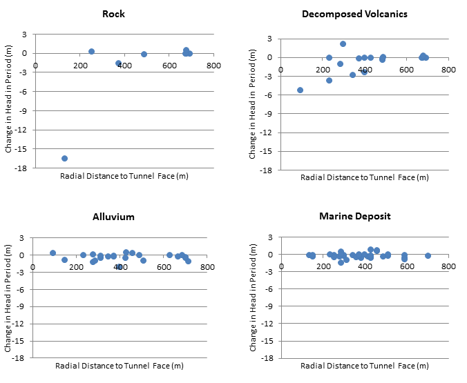
The graphs in Figure 7 show the change in piezometer head against radial distance to tunnel face which occurred as a result of mining in this section. In rock there is a clear drawdown in only one of the piezometers and this is the nearest to the tunnel. A steep drawdown curve can be seen in some piezometers but others show no response despite being relatively close. This is due to the control of rock structure and connectivity on transient water flow. In the decomposed rock (CDV) a wider drawdown curve can be identified with affects seen as far as 400m from the tunnel face but still several piezometers are unaffected as would be expected with the decomposed rock inheriting many of the characteristics of the rock. The alluvium by contrast shows no recognizable drawdown curve but affects are observed as far as 700m from the tunnel source. Many piezometers are unaffected and there is no correlation with radial distance. Since the marine deposit also relies on the alluvium for its connection to the sink it is no surprise that the marine deposit shows the same relationship. The results suggest that the use of simple layer cake homogenous hydrogeological models is not valid for transient water inflow studies. Their use should be restricted for assessment of steady state water balance analyses only and not used for assessment of the likely lateral extent of water drawdown effects. For this more regional hydrogeological drainage models should be constructed.
5. Control Measures
Control measures implemented within deep tunnelling projects are typically limited to pre-grouting at pre-determined intervals, based on simple models of rock permeability combined with remediation grouting when inflows continue and / or exceed the rate of allowable discharge. During shallow tunnel construction, for instance by cut and cover methods, groundwater is typically controlled by implementation of a cut off (diaphragm walls, secant pile walls, grout curtains etc) and a recharge system, which is often a series of recharge wells places at pre-determined spacings with little understanding of the complexity of the hydrogeological conditions. The difficulties in creating a successful recharge system are well recorded, notably in CIRIA C515 (Preene et al., 2000). The primary consideration is whether compressible materials that are of concern can be recharged directly or whether recharge should be targeted at surrounding, more permeable facies which will prevent under-drainage in the first place. The concept that low permeability materials will not readily accept recharge is logical yet apparently overlooked in the majority of recharge system designs. In addition to targeting recharge wells to intercept suitable facies, issues of groundwater chemistry and suspended solid content within the recharge water often leads to clogging and bio-fouling of the wells with the net result that a systematic programme of maintenance is essential and many contingency wells must be installed, in addition to the original design number, in order to maintain the design quantity of wells in operation while maintenance is ongoing. Recharging too close to the sink may also result in excessive feedback, where additional grouting / pumping solutions are then required within the tunnel to deal with the extra inflows. Recharge schemes fail due to a limited understanding of the hydrogeological complexities of the surrounding environment and the assumption that an holistic recharge of that environment is necessary and can be achieved. In addition to the recommendation that facies maps are adopted during the planning and design stages to model groundwater movement those receptors sensitive to groundwater drawdown in the surrounding environment should be recognised and targeted for analysis. Where groundwater drawdown is controlled by fissure flow and palaeo-channels, and not simply primary permeability of overlying units, drawdown may not occur above or adjacent to tunnel alignments but also at some lateral distance from the tunnel. Having undertaken a facies mapping exercise and recognized the potential flow paths across the wider area surrounding the alignments, control of groundwater around specific sensitive receptors should then be considered in addition to any cut-off, grouting or recharge adopted at the tunnel site. Sensitive receivers may vary from concern for surface habitats, including protection of river systems’ base flow, particular ecosystems or crops, to excessive settlement, distortion, damage or collapse of slopes, utilities, infrastructure and buildings. In addition to consideration of annual mean rainfall, protection of surface habitats could include the use of shallow trench recharge systems or sprinkler systems. Targeted protection of slopes, utilities, infrastructure and buildings may rely on a combination of local groundwater cut-off and recharge systems around the receptor of concern, taking into account the underlying hydrogeological conditions, foundation type and particular risk of that receiver. The authors are aware of at least one current project in Hong Kong where an existing tunnel is being protected in this way while the construction of new tunnel proceeds beneath it.
6. Conclusion
In most tunnel projects where water is strictly controlled, it is the transient behavior of ground water which is of key concern. In this regard it is the higher permeability materials which are most important and in particular those which are compressible and have restricted recharge. These include CDG/CDV deposits in fault zones, sand pockets in alluvial systems and some re-deposited clays including those in seawalls and beneath dredged reclamations. In the transient case detailed engineering geological and hydrogeological subsurface mapping is recommended ahead of numerical modeling. In complex hydrogeological settings modeling should be aimed at sensitivity testing and identifying the likely relative contributions of recharge and discharge in certain key areas. Groundwater control measures must take into account the complexity of the model produced and target recharge at appropriately receptive facies in areas where key sensitive receptors have been identified.
References
- Lee C.H. and Farmer I.W. 1993 Fluid Flow in Discontinuous Rocks. Chapman & Hall, 1993
- Fookes P.G.E, Lee, M., Griffiths J.S. 2007 Engineering Geomorphology: Theory and Practice
- Preene, M., Roberts, T.O.L, Powrie, W., Dyer, M.R., 2000, C515 Groundwater Control — Design and Practice, CIRIA
- Leeder M. Sedimentology and Sedimentary Basins 2011 Wiley Blackwell
- Reilly, M.R.W. 2007 Facies Distribution within a Dryland River Channel and Terminal Splay Complex. Umbum Creek, Lake Eyre, Central Australia. Unpublished PhD Dissertation, The University of Adelaide, Adelaide.
- Territory Development Department of the Hong Kong Government (2000) Investigation of Unusual Settlement in Tseung Kwan O Town Centre
